|
|
| Click on image for video | Click on image for full size |
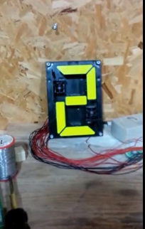
The aim of this experiment is to control a Signalex seven segment display using the Arduino, a pair of shift registers and two MIC5801bn drivers.
Each segment is controlled by a center tapped coil. The ends of the coil are connected to red and orange wires. The center is a black wire. So each segment has three wires: red, black and orange. We are using the mic5801bn, so the black wires will be +12v. Grounding the orange wire causes the segment to show the YELLOW side. Grounding the red wire causes the segment to show BLACK. Grounding both wires at the same time is a bad idea.
The orange and red wires are connected to a 16 pin connector but the black wires are crimped together and one common black wire appears on the connector. The black wire is on pin 1 of the connector. The red wires are on pins 2 to 8 and the orange wires are on pins 9 to 12 and 14 to 16 (pin 13 is unconnected).
The segments in a seven segment display are identified by the letters A to G as shown in the diagram below.
| Socket Pin | Colour | segment | Socket Pin | Colour | segment | Segment Diagram |
|---|---|---|---|---|---|---|
| 1 | black | +12v | 9 | orange | E | 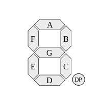 |
| 2 | red | C | 10 | orange | G | |
| 3 | red | D | 11 | orange | F | |
| 4 | red | E | 12 | orange | D | |
| 5 | red | G | 13 | n/c | ||
| 6 | red | F | 14 | orange | C | |
| 7 | red | B | 15 | orange | B | |
| 8 | red | A | 16 | orange | A |
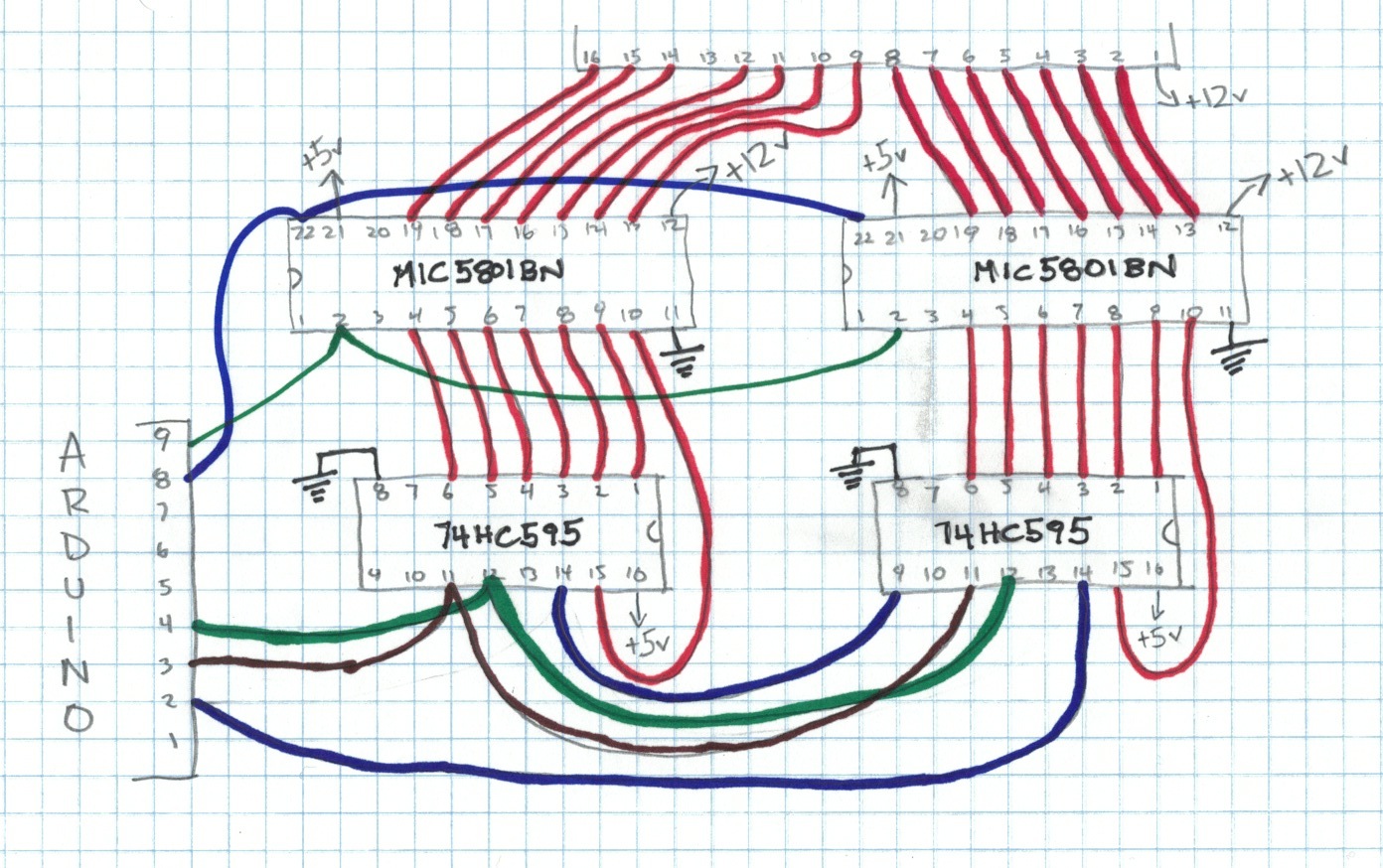
The signalex requires 12v and EACH segment requires a current of about 120mA. Therefore logic chips cannot connect directly to the signalex (well, you can connect it directly but it doesn't work). The signalex requires a 12v high current driver. I will use the mic5801BN because this chip was present on the board I salvaged from the old race clock. The mic5801BN has eight input pins, eight output pins, a common supply pin, an enable pin and a strobe pin. I will use two mic5801BN chips. The common supply pins are connected together then connected to +12v and the black wire from the signalex. The orange wires from the signalex connect to outputs 0 to 6 of one mic5801bn and the red wires connect to outputs 0 to 6 of the other. The inputs of the mic5801bn are connected to the output pins of a pair of shift registers.
Each output pin is controlled by its own input pin. The input pins work at normal TTL. When the input pin is low, the output pin is in a high resistance state. When the input pin is high, the output pin enters a low resistance state and current flows to ground. So the input pins control whether or not the output pins are grounded.
The two shift registers are connected in series. Shift register 0 controls the orange wires, shift register 1 controls the red wires. Because the red and orange wires are in a strange order on the signalex connector, the outputs of the shift registers may correspond to different segment on the red and orange wires. The table below shows how the shift register output pins correspond to control wires of the signalex digit.
| Shift Register 0 | Shift Register 1 | Segment Diagram | ||||
|---|---|---|---|---|---|---|
| Output | Colour | segment | Output | Colour | segment | |
| 0 | orange | C | 0 | red | E | |
| 1 | orange | D | 1 | red | G | |
| 2 | orange | E | 2 | red | F | |
| 3 | orange | G | 3 | red | D | |
| 4 | orange | F | 4 | red | C | |
| 5 | orange | B | 5 | red | B | |
| 6 | orange | A | 6 | red | A | |
Each digit has a different arrangement of on and off segments. For instance, to show the digit zero, segments A to F are all ON and segment G is off. Therefore to show a zero, register 0 outputs 0 and 2 to 6 must be ON and output 1 is OFF. This forces the A to F segments to show YELLOW. Register 1 controls which segments show BLACK. The G segment is off, so register 1 output 3 must be ON which will force the G segment to change to black. Expressed as ones and zeros, register zero pins 6 to 0 are 111_1101 and register one pins 6 to 0 are 000_1000. These are the binary expressions of the decimal numbers 125 and 8.
The table below shows the bit mappings.
| Digit | Segment | Register 0 (Orange) | Register 1 (Red) | ||||||||||||||||||||
|---|---|---|---|---|---|---|---|---|---|---|---|---|---|---|---|---|---|---|---|---|---|---|---|
| G | F | E | D | C | B | A | 6 | 5 | 4 | 3 | 2 | 1 | 0 | byte | 6 | 5 | 4 | 3 | 2 | 1 | 0 | byte | |
| 0 | off | on | on | on | on | on | on | 1 | 1 | 1 | 1 | 1 | 0 | 1 | 125 | 0 | 0 | 0 | 1 | 0 | 0 | 0 | 8 |
| 1 | off | off | off | off | on | on | off | 0 | 1 | 1 | 0 | 0 | 0 | 0 | 48 | 1 | 0 | 1 | 1 | 1 | 1 | 0 | 94 |
| 2 | on | off | on | on | off | on | on | 1 | 1 | 0 | 1 | 0 | 1 | 1 | 107 | 0 | 0 | 1 | 0 | 0 | 0 | 1 | 17 |
| 3 | on | off | off | on | on | on | on | 1 | 1 | 1 | 1 | 0 | 1 | 0 | 122 | 0 | 0 | 1 | 0 | 1 | 0 | 0 | 20 |
| 4 | on | on | off | off | on | on | off | 0 | 1 | 1 | 0 | 1 | 1 | 0 | 54 | 1 | 0 | 0 | 0 | 1 | 1 | 0 | 70 |
| 5 | on | on | off | on | on | off | on | 1 | 0 | 1 | 1 | 1 | 1 | 0 | 94 | 0 | 1 | 0 | 0 | 1 | 0 | 0 | 36 |
| 6 | on | on | on | on | on | off | on | 1 | 0 | 1 | 1 | 1 | 1 | 1 | 95 | 0 | 1 | 0 | 0 | 0 | 0 | 0 | 32 |
| 7 | off | off | off | off | on | on | on | 1 | 1 | 1 | 0 | 0 | 0 | 0 | 112 | 0 | 0 | 1 | 1 | 1 | 1 | 0 | 30 |
| 8 | on | on | on | on | on | on | on | 1 | 1 | 1 | 1 | 1 | 1 | 1 | 127 | 0 | 0 | 0 | 0 | 0 | 0 | 0 | 0 |
| 9 | on | on | off | on | on | on | on | 1 | 1 | 1 | 1 | 1 | 1 | 0 | 126 | 0 | 0 | 0 | 0 | 1 | 0 | 0 | 4 |
| A | on | on | on | off | on | on | on | 1 | 1 | 1 | 0 | 1 | 1 | 1 | 119 | 0 | 0 | 0 | 0 | 0 | 1 | 0 | 2 |
| b | on | on | on | on | on | off | off | 0 | 0 | 1 | 1 | 1 | 1 | 1 | 31 | 1 | 1 | 0 | 0 | 0 | 0 | 0 | 96 |
| C | off | on | on | on | off | off | on | 1 | 0 | 0 | 1 | 1 | 0 | 1 | 77 | 0 | 1 | 0 | 1 | 0 | 0 | 1 | 41 |
| d | on | off | on | on | on | on | off | 0 | 1 | 1 | 1 | 0 | 1 | 1 | 59 | 1 | 0 | 1 | 0 | 0 | 0 | 0 | 80 |
| E | on | on | on | on | off | off | on | 1 | 0 | 0 | 1 | 1 | 1 | 1 | 79 | 0 | 1 | 0 | 0 | 0 | 0 | 1 | 33 |
| F | on | on | on | off | off | off | on | 1 | 0 | 0 | 0 | 1 | 1 | 1 | 71 | 0 | 1 | 0 | 0 | 0 | 1 | 1 | 35 |
So if I want the number 0 to appear on the SIGNALEX, then I shift out the number 125 then shift out the number 8.
/*
 *   signalex 1
 *
 *   the arduino pushes two bytes to a pair of shift
 *   registers. the registers control the elements of
 *   the signalex digit
 *
 *
 */

byte dataPin = 2;
byte clockPin = 3;
byte latchPin = 4;

int mic5801StrobePin = 9;
int mic5801EnablePin = 8;

byte numbersToSignalex[16][2]= {
  {125, 8},
  {48, 94},
  {107, 17},
  {122, 20},
  {54, 70},
  {94, 36},
  {95, 32},
  {112, 30},
  {127, 0},
  {126, 4},
  {119, 2},
  {31, 96},
  {77, 41},
  {59, 80},
  {79, 33},
  {71, 35}
};


void setup () {
  pinMode(dataPin, OUTPUT);
  pinMode(clockPin, OUTPUT);
  pinMode(latchPin, OUTPUT);
  pinMode(mic5801EnablePin, OUTPUT);
  pinMode(mic5801StrobePin, OUTPUT);

  //  initialize 5801 (disable it)

  digitalWrite(mic5801EnablePin, HIGH);
  digitalWrite(mic5801StrobePin, LOW);
}

void loop () {
  int delayTime=250;

  for (int i=0; i<16; i++) {
    updateSignalex(numbersToSignalex[i]);
    delay(delayTime);
  }

}

/*
 *   shiftOut(byte dataPin, byte clockPin, byte bitOrder, byte value)
 */

void updateSignalex(byte value[1]){
  digitalWrite(latchPin, LOW);     //Pulls the chips latch low
  shiftOut(dataPin, clockPin, MSBFIRST, value[0]); //Shifts out the 8 bits to the shift register
  shiftOut(dataPin, clockPin, MSBFIRST, value[1]);
  digitalWrite(latchPin, HIGH);   //Pulls the latch high displaying the data
  digitalWrite(mic5801StrobePin, HIGH);
  delay(1);
  digitalWrite(mic5801StrobePin, LOW);
  digitalWrite(mic5801EnablePin, LOW);
  delay(250);  // energize the coils for 250ms
  digitalWrite(mic5801EnablePin, HIGH);
}